Sculpties direct from Rhino 4?
Rhino 4 is professional 3D CAD system. In my first life as mechanical engineer, I prefer Rhino to SolidWorks which costs nearly five times more. And for SL purposes, SolidWorks is totally useless...except for the fact that SolidWorks models can be imported into Rhino and thence from there into Second Life.
The good folks at McNeel Assoc who distribute Rhino have begun work on a direct export feature for Second Life sculpties. But it is early days yet and their efforts-to-date, while encouraging, are not yet commercially ready. For those of you eager to play and possibly contribute, here is what they have very graciously shared with me so far.
Download: ZIP — Experimental SculptedPrims.rhp plugin, all the source code, etc (current as of 2008-04-09)
That will get you these new Rhino commands (experimental — don’t expect a whole lot just yet). But try them out, encourage the company, and do offer to help out as much as you can. (I would myself if I knew any C++ at all. But I do not, being a Perl programmer instead.)
SculptedPrimSurfSculptedPrimMeshMakeSculptedPrim
Anyone from the community of programmers in Second Life is encouraged to contribute to the further development of this open source project.
Get Info: Wiki — Rhino public software development kit.
Related Info: HTML — How about importing *.3dm files directly into SL? Vote for this!
Sculpty theory for dummiessculpt_theory
Sculpties enjoy technical explanations aplenty on SL blogs. I cannot improve on those. Let me instead explain about sculpties by painting a picture in your mind while still using only words. Here begin my thousand words to describe a picture.
A Net of White Beads
Let us consider the simplest shape imaginable, a sphere. Picture a blue, featureless globe of the Earth (as if it were all ocean without any land). Picture it having vertical longitude lines dividing the globe into grapefruit wedges and horizontal latitude lines slicing it sideways into cake layers. Picture it exactly like a flag of the United Nations. On that flag they show 36 grapefruit wedges for longitude and 18 cake layers for latitude.
The grapefruit-wedges number 36 as do the lines between them because they go full circle. Following around that full circle you start and finish in the same place. The last line and first line are the same. So 36 lines between each of the 36 grapefruit wedges.
Cake layers are stacked, however. So in between those cake layers are one fewer boundary divisions than there are layers. And besides, you need an odd number in order for there to be an equator. So only 17 lines may be counted between the 18 separate cake layers. Or call them 19 if you want to include the top and bottom surfaces. An odd/even boundary-versus-layer mismatch either way you look at it. Simple enough.
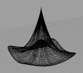
Next imagine those 36 x 17 lines becoming black wires. Now we have a blue globe in a cage of black wires like a hair net. Now let the blue globe disappear so only the black wires remain. This leaves us with an empty cage of black wires very like the UN symbol.
Let us now add some white beads. At every criss-crossing of two black wires add a white bead. Said bead centers exactly on the crossing so that the wires make their criss-cross in the very center of said white bead.
Now add two more white beads, one each at the north and south poles. Before us now is a something like a hair net of white beads wrapped around an invisible globe.
Lastly imagine this whole arangement floating in space. In space you cannot see the black wires. With the wires not showing we see only a spherical matrix of pure white beads floating in space..
Tri-colored beads for X, Y & Z
While our floating ball of white beads strung on (invisible) black wires hangs in space next we’ll shine colored lights upon it from different directions. From the left (the X direction) we shall shine red light upon it. Whichever bead lay closest to left will be very brightly red. Whichever bead lay furtest away will be only dimly red.
From the top (the Y direction) we shall now also shine a green light. Now in addition to beads having red light they also now have varying degrees of green. Those which are are near the top will be very brightly green. Those near the bottom will be only dimly green. The red light still also shines upon them. So every bead has red and green light both upon it depending on how close each bead is to each light respectively.
Now put on a miner’s hat with a blue lamp in the front. See how every bead now has also blue light upon it. Whicever bead lay closest to you will be very brightly blue. Whichever one lay furtheset away will be only dimly blue. And still both the red and green lamps shine upon all, each with brightness depending upon proximity.
Now imagine that every bead absorbs the tri-color light shown upon each. Those colors get hard-baked onto the surface of each and every bead. We can turn off the lamps and still each bead retains its color. Our ball of beads now glows by itself with a whole rainbow of hues. Each tri-color bead tells you exactly where it belongs in 3D space by its combination of hues.
And what if a bead should just so happen to lay in the very center, half way between all three colored lights? That bead would be middling dull red, middling dull green and middling dull blue...all at once. That works out to a kind of gray.
So we’ve got this pretty ball of mostly rainbow-hued beads with maybe some grayish ones in the mix. What possible good is it? Well, knowing each bead by its color, and knowing also each bead’s position releative to its neighbors, we know all there is to know about both their collective shape and position in 3D space. We know it two ways, by color and also by arrangement. With this information we can easily make a map. Let’s do that now.
Making a seam
Looking at our ball of brightly glowing beads let us choose any one from among the 36 vertical longitude (grapefruit wedge) wires. All maps need to lay flat. That is the purpose of a map. To make it lay flat will require some careful surgery.
First we shall need a seam. We choose any one of the vertical longitude (grapefruit wedge) wires. Taking scalpel in steady hand we slice that one longwise, beads and all, into halves. We start at the equator bead and cut an incision upwards, carefully spliting the back wire longwise and every bead strung upon it. We pause when we get to the north pole bead.
The north pole bead we don’t cut in half. We only cut halfway into the north pole bead. Now we cut southward from the equator. Similarly we stop when whe have cut half way into the south pole bead. Now our fine, rainbow hued ball of beads looks to have a zipper in it. An open one. Let us hope that nothing untoward falls out.
So we’ve got this perfect seam and still our bead-on-wire arrangement will not lay flat. It won’t lay flat because that pair of north- and south-pole beads still hold it together at top and bottom. Let us have a look at those.
Parting the poles
These two beads at the north and south poles are different from all the others. They each join not a simple criss-cross of just two wires but instead a spoked wheel of 36 pie wedges. Along whe middle of the black wire which we had chosen for our seam, each bead north and south is cut half way through as was needful to complete the seem. We only need a single seam. So the other 35 black wires we’ll leave unmolested. We still need to separate them one from the other.
To separate the black wires where they join at the poles we will need to even further divide up the north- and south-pole beads. We’ll cut those beads into grapefruit sections by slicing, not through the remaining 35 wires, but in between them toward the center of each bead. This will give us 37 (not 36) grapefruit-wedge-shaped fragments for each pole-bead, north and south.
Why 37 and not 36? Remember our first original cut...the one required to complete the seam? That cut split into halves one of the grapefruit-wedge bead fragments. So 37 pole bead fragments, with two of those each being half as thick as the others. North and south, both pole beads are divided into 35 full-width grapefruit-wedge sections and two only half-width. The half-width sections each have only half a wire, which likewise bears only half-beads along its length.
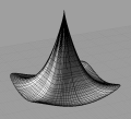
Now it is undone enough so that we can lay it flat. It bunches up some at the equator because the equator wire is longer than any other of the remaining horizontal, cake-layer wires. But we’ll ignore that for the moment. Bunched up in the middle or not we’ll lay it out as flat as we can onto a black cookie sheet. We put this cookie sheet into an oven.
Baking a sculpt map
In the oven the black wires soften and slump. Those beads which had once held in a humped up position because of their wires, settle down int a perfect square pattern. The back wires disappear completely. All we can see resting on the black cookie sheet is perfect square of rainbow-hue, blobs.
Looking at our square of rainbow-hue blobs lying on their black cookie sheet, we notice that all of the cut-in-half beads lay at opposite ends of the cookie sheet to left and right. All of the grapefruit-wedge, pole-bead fragements lay at opposite ends to top and bottom. At each of the four corners is a single cut-in-half, grapefruit-wedge, pole-bead fragment.
That means the whole top row of rainbow-hue bead fragments each reperesent a single bead, the north pole. Similarly, the entire bottom row of of bead fragments are just the south pole. The whole left column of half-beads, represent one half of the seam. And likewise, the entire right-most column represents the other half of that same seam. This is exactly what a sculpt map represents.
As the oven temperature rises, the rainbow-hue beads and bead fragments melt into equal-sized, rainbow-hue dots on the black paper. We take it out and have for ourselves a flat graphic map which represents a round globe very exactly and precisely.
What’s still wrong with this picture?
Remember where we took the Earth’s globe as our starting example? And because of that our scuplt map has dots arranged in a rectangle of 37 x 19? That numbering scheme is not very good for computers. Computers hate irregular combinations like that. So sculpt maps are square. They have to measure at some nicely even multiple of 32 x 32.
While 32 x 32 is okay, you’ll mostly find them at 64 x 64 or even 128 x 128. Bigger is better, but not beyond 128. Anything higher than 128 is just a waste and causes unnecessary lag. You don’t get any more resolution for having doubled or quadrupled the count. All that it does is help SL deal with a little problem it has uploading colors. If you provide just 32 it will upload mostly intact. If you send it 128 then it will get there fully intact. It has to do with lossy compression algorithms which I shall not go into here.
Shape limitations
Every sculpty for second life currently uses the sphere-like, color mapping detailed above. Imagine that you have a sphere and can beat it into almost any shape you want. One of the things you cannot do is bore holes into the surface. You can pinch and dent it inward. But you cannot bore any holes clear through it.
Tight corners can also be tough. Bear in mind that the sculpt map only shows where grid-line criss-crosses meet and where vertical lines join like wagon spokes at each pole. The proper name for such an intersection is vertex, and in plural vertices. The actual sculpty is not these vertices alone, but them together with the surface areas stretching between. Knowing where the vertices lay suffices to know also how the surface must stretch between them. So a sculpt map need only contain positional data for vertices. The in-between suface areas are inferred. They just happen.
Those in-between surfaces might just happen, but they do not always happen quite how you might expect. Turn too sharp of an inside corner and you will find that unaccounted for in-between surface stretching across an in-between void just where you do not want.
Also take care to note as how the web of surface can even pull away from any given vertex if two or more other vertices pull it harder the other way. So you have to think of the un-accounted for surface as not super-glued to every vertex, but only strongly attracted to them. Think of the surface as a sheet of nearly invisible, stretchy rubber. Lay this sheet upon the square of rainbow-hued beads. Magnetize both, so that the sheet very much wants to stick to every bead in just the place where it now lay.
Now when you move a bead (which we should properly call a vertex) the nearly invisible rubber sheet wants to try and follow that bead. But the other beads are drawing it too. Pull that one bead too very far away from the rest and the sheet will follow only so far as it can. There, having stretched its furthest, it will hang as a bulge in the sheet questing for the unreachable bead.
How do you overcome that? Group your vertices closer together in those regions. If you need the sculpty surface to make a sharp corner, be it an inside or outside corner, group your vertices closer there so that they may tug all together. Any place where the scuplty fabric lays fairly in a straight line, you don’t need many vertices there.
Impenetrablility
All sculpties, alas, are impenetrable. If you need to penetrate them, even if they are a bowl, they need to be phantoms. This is set in your SL create/edit mode for whatever object you sculpt-map comprises. I trust SL to fix this problem in due course. But for now that’s how it is.
Semi-automatic methods
I know of no direct and easy way to obtain quality sculpt maps from *.obj files. Here, however, is a passable work-around. It consists of inflating proto-sculpties inside a wire-frame mesh.
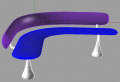
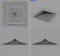
 16-Sculpty Rhino 4 Model
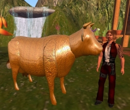 How now bronze cow?
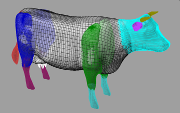
This cow is one I made for import into Second Life using the Rhino 4 CAD system. Each color represents a proto-sculpty, that is to say, a NURBS sphere object. This cow-shaped collection of NURBS spheres are now ready for conversion into sculpt maps. That I will do by dragging its Cow_for_SL.3dm file onto the 3dm2sculpt.exe function the same as always.
The really cool part is how easy it was to mold those 16 separate NURBS spheres into the desired cow-part shapes. It only took me two evenings thanks to the FillMeshWithSphere.rvb script very kindly provided by Pascal Golay of Robert McNeel and Associates (publishers of Rhino 4). He wrote it for me in response to a query I posted on their News portal. Thank you Pascal!
Pascal permits me to re-distribute this script for free on the condition that it be accepted as-is, that is to say freeware, with all the usual caveats and disclaimers. Pascal and his employers provide no support and are accorded full immunity even should the sun go out as a result of your using it.
The script works like so... Imagine that you place a spheroid balloon inside a wireframe sculpture and slowly inflate it as far as you reasonably could. Our theoretical balloon is much like its real-world counterpart in being not perfectly supple. So we can't make it to fill every cranny perfectly. Nor will it flow around corners. But even so the results are quite good. To fill any tight spaces or turn any bendy elbows we just have to use more balloons.
Use it like so...
- Unzip this file ZIP to anywhere.
- It unpacks to a pure-ASCII text file named
FillMeshWithSphere.rvb
- Drag the script into any one of the Rhino 4 windows.
- Type
FillMeshWithSphere into the Rhino 4 command widget. It will ask you to...
- Select any fully closed mesh.
- Select a virginal default sphere pre-placed inside said mesh.
- Wait patiently while Rhino 4 works its wonders...
- The original default sphere is rebuilt to 16x32 UV dimensions.
- Said sphere is next inflated step-by-step, with all control points moved radially outward.
- The script exits when all points have been pushed up against the nearest mesh surface.
- Which is why it won't flow around corners.
- Control points can poke out through a hole, though. And this will cause an error.
Inflating a cow
It took me a few tries to get the above results. The trick is in how one divides up the mesh. This I did by splitting it with NURBS spheres and ovoid cylinders as suited the local geometry. Having experienced some minor sculpty-shrinkage phenomena previously I was careful to split not a single mesh, but paired copies. This way I could be sure of having some overlap material with each split out section. Having overlap assures no gaps in later re-assembly.
Then I had to close off the holes that resulted from spliting the mesh. Usually I could do that easily with FillMeshHoles. When that worked then I was ready to just insert a virgin sphere and call the script.
One time, however, calling FillMeshHoles made a big mess. It was on the front upper leg. That edge was just too raggedy. Rhino's attempt to close off that ragged hole only worked less than 100%. A bunch of tiny holes were left. If any control points get pushed out such a hole then the operation fails so that you will have waited in vain.
To fix that problem I had to go back and manually trim the hole's edges and make them pretty. I did this by repeatedly calling DeleteMeshFace to individually remove a whole lot of ugly splinter-like facets leaving only nice clean big ones. That took a lot of trimming. So it was especially good that I'd started with plenty of overlap material. Trimming complete, I then had to maually close the hole with repeated calls to PatchSingleFace building a cover over the hole one triangle at a time, the bigger the better. That done, I popped a virgin sphere into the closed off shoulder and called the script.
The lower feet were another problem. Being kind of skinny and not well suited to balloon inflation I found it helps to first distort their proportions using Scale2D by 4 for the sphere-inflation and then later calling Scale2D again by 0.25 to undo the swelling.
The tail turned out to be impossible. It was just too twisty. So I made a tail the old fashioned way by creating a sphere. This I next stretched out long and straight, adding extra knots to make it pipe-like. Manually dragging control points got it looking poofy at the swishing end. Then I made a call to the FlowAlongCurve function to obtain the curvy pose.
Higher resolutions
The script is pure text. So it is easy to view and edit. Mostly it reads like Klingon to me. But one thing is so obvious I was tempted to experiment with it. So I changed lines 18 & 19 in my copy to read like so...
			Dim SampU: SampU = 64
			Dim SampV: SampV = 64
...thereby increasing the NURBS sphere resolution to UV 64x64 from 32x16. My previous experiments show that doing so sometimes helps 3dm2sculpt.exe to make clearer sculpties even though its own output can not be higher than the sculpty limit of 32x32. I assume that Cindy Crabgrass has it doing something pretty clever in there. Setting it to 32x32 will most likely approximate the quality of what most sculpty-creation methods afford. Going higher does makes sense though. I do that to get an overall tight knot concentration to insure high UV-knot density in areas where feature density is high. Then I later reduce the knot count manually by removing knots from regions of lower feature density.
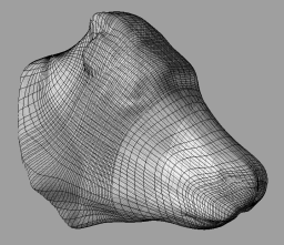
On my own Dell M6300 with 3MB an effort to obtain clearer definition around the eyes of my cow-head sculpty pictured above by running 128x128 crashed from lack of memory after half an hour. My next attempt at 96x64 ran fine.
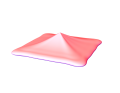
 UV 96x64 adjusted to 77x100
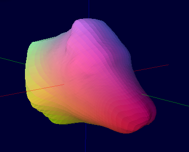 Smoothed in SculptyPaint
 Sculpt Map
 Second Life
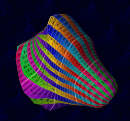
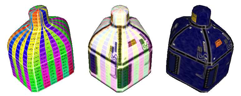
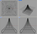
Above you see the process results up to, but not including, final texturing. It problably looks like I've wasted a lot of effort to preserve features sure to be lost in the final UV 32x32 result. But who knows if in a year or two Linden Labs might start supporting higher resloution sculpted prims? All I'd need do is crank out a new map and drop it on the existing prim. But for now this is what we get. Left-to-right, they are...
- Last stage in Rhino hand-weaking the knot locations.
- Inside SculptPaint after smoothing.
- The 128x128 sculpt map output by SculptyPaint.
- Rezzed inside Second Life and with my pre-paint custom test pattern applied.
- Applied is a texture of a 32x32 grid (numbered in base-32 from 00 at top-left to vv at bottom right.
- Every square actually aligns with the sculpt map's UV vertices.
- So I can look at it and paint (laboriously) in 2D for a 3D wrap-around.
Texturing toolstemplates
Just like sculpt maps, textures are 2D graphic files made for use on 3D objects. Basically, textures are like paintings on flat sheets of rubber that your computer graphics card wraps around a 3D shape to give it, obviously enough, texture. Without this texture wrapped around it, the shape is either invisible or nearly so.
Very expensive 3D paint programs hold up the actual 3D model for easy painting on each side in turn using the mouse. Most of us have to make due without such an expensive convenience, however. For that we require a less costly work-around method. Chief among these is the use of templates.
When you wrap a 2D graphic (photo, painting, whatever) around a 3D object model the computer only gives you two choices: default and planar. For both sculpties and avatars you nearly always want the default. The default is to wrap it so that the square edges of your graphic fit along a seam on the surface of the 3D model.
On avatars that seam is rather complex but always exactly in the same place. On sculpties that seam is very simple but can be almost anywhere at all. And wherever there is a seam on the 3D model your graphic must be either featurelessly uniform or else perfectly aligned. The former is ugly and obvious. The latter can be agonizingly difficult. A template will help to achieve the latter. A template will pinpoint where the seam is and how it aligns.
Custom templates
If you want to design SL clothing, very good templates already exist. All you need do is search the SL blogs to find them. Books on SL content creation also provide them on accompanying CDROMs. Prior SL content creators have made these for their own use and generously share them with all.
Human SL avatars are based on one of two 3D models: male and female. Changing your shape does not change the basic elements of that model. Changing your shape only works to inflate or lengthen certain dimensions of that model. A template is an outline of the very 3D model itself, displayed in 2D format. So one of two templates is all you need to design clothing for any shape.
Pre-existing custom templates are useless for texturing scupties because the basic 3D model itself varies wildly from object to object. So sculpty designers have to make due with generic templates as a guide.
I’ll say no more about custom templates since this how-to is all about sculpties.
Generic templates
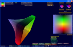
Here are two generic templates, both very useful as alignment guides in texturing sculpties. On the left is a 20x20 resolution test pattern freely distributed both on-line and in books like "Second Life, A Guide to Your Virtual World". It was designed by SL resident Robin Sojourner. You will find it very useful most of the time. On the right is a 32x32 resloution test pattern designed by yours truly. I hope you might find it equally useful the rest of the time.
Which of the two will prove the most useful will vary depending upon how large or complicated your sculpty design happens to be. For medium to very small items, the one by Robin Sojourner will surely serve best. For use with really big designs you might like mine better.
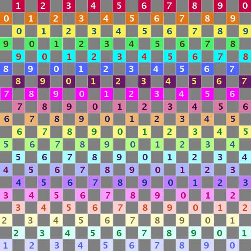 20 x 20 Pattern
by Robin Sojourner
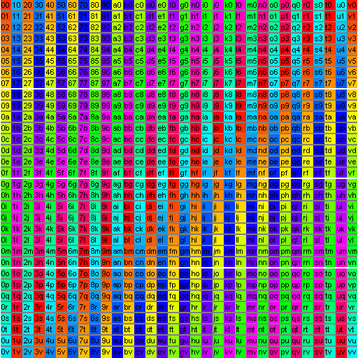 32 x 32 Pattern
by Aplonis Ember
Let us compare them. Each is good in its own way. Robin’s has a repeating pattern of numbers. Every square on my template has its own unique number-and-letter combination. On large objects it can be hard, using Robin’s template to know quite which square you are looking at because you cannot see the whole thing, or see the back side. The number-and-color combinations are unique, true. I still find it hard, sometimes. On small objects the font on mine becomes nearly unreadable, though. They compliment each other in this regard. So it is good to have two templates: one each for different sizes.
I myself use Robin’s often and only had need of making a new one when I got into much larger objects. That and upon occasion it sometimes helps to blow an object up really large, even up to the 10-meter limit. Then I can float my avatar beside it, use mouselook, and be my very own microscope. In those cases too a more detailed test pattern often proves handy. Come the day when VR graphics improve enough, we all might have need for a 64x64 pattern. Progress like that always happens sooner than anyone expects.
One very important feature of my pattern shows up poorly, if at all, on this web page, owing to the light color background. Know, however, that in addition to the three, white, 2-pixel-high, hoizontal rows there are also a pair of white, 1-pixel wide, vertical lines. These align with the seam of a sculpty. These are the left-most and right-most columns and measure only one pixel wide. They are only a pixel wide because when they join at the seam of a sculpty in your 3D view on SL, then they merge as a single, white, 2-pixel wide, seam indicator. This makes the seam quite easy to find.
Right click on each one in turn and do a Save As to someplace convenient.
How I made it
Don’t be too impressed with how much effort it was to get such fine detail on a 32x32 resolution pattern. It really wasn’t hard at all. I cheated on that part by writing a Perl script.
Not too many lines of Perl was all it took to generate those fine details as pure ASCII in SVG format. I then viewed the SVG in Firefox and clipped it from off the screen using GIMP. It came off pixel-perfect because I stuck only to formats like SVG and PNG. If Robin’s looks a little fuzzy when blown up large, that is because JPEG suffers horribly from lossy compression. Most of the time it doesn’t matter. But in the particular case of a 32x32 pattern it surely would have. The font which I had to use is so small the dot on a lower-case i is just one pixel.
Then, after I’d played around with the new pattern a bit, I decided it could also do with white lines to denote the sculpty seam at LH and RH. Being lazy, rather than starting over with a modified Perl script, I just decided to paint those in manually using the GIMP. And while I was at it, I figured why not also trisect the matrix vertically. So I did. Hope these features suit your needs as well as mine.
Using templates
To use a template you need to have a drawing program that lets you use layers. Layered drawing is like having an entire pad of tracing paper where you can draw different parts on differnt sheets and see them all, or not, depending on how transparent you make that sheet. The base (lowest) layer could be for outlines only. The next layer up might be pasted-in clips from photos. The one above that might be text. And so on... The top layer, at say, 75% to 95% transparent, will be your template.
You start out with two layers, the base upon which you have nothing drawn yet, and the top with only the template. Layered drawings do not upload into SL. So you export a copy of this in PNG format. Always choose PNG, never JPEG...unless you really want it fuzzy and indistinct.
 Pattern to texture
in plural stages.
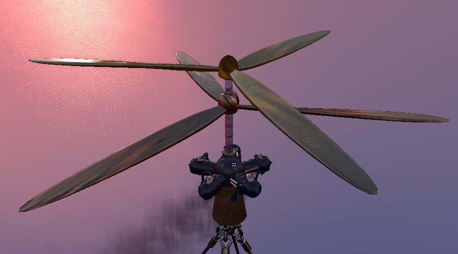
What is that thing? See these pics...
Link 1
Link 2
Early trials
I recommend starting out with Robin Sojourner’s 20x20 template. That way you can proof your model off-line from SL using SculptyPaint. My own 32x32 template displays poorly in ScuptyPaint because of its very tiny font. ScultpyPaint has, of course, its own built-in template. But that one assumes you like counting pixels. I do not. I love SculptyPaint however because it saves me lots of bother uploading try-out textures into SL, not to mention wasting all those L$10 upload fees.
Look at your sculpty wearing the templated try-out texture and decide how you want to proceed with editng. Make some additions and/or changes to the texture in the layered drawing program, re-export and re-view it in Sculpty paint again. It’s really quite easy, working off-line that way. Saves for a lot of frustration.
Final trials
Once you are mostly happy with your texture in all those areas away from the seam and areas of high contour distortion comes the time to upload trial textures for last-round modeling in SL itself. Each such upload will cost $L10, though. So don’t be hasty and jump ahead to this step too early. Be sure that now is really the time to focus only on those areas near to the seam, poles and high-contour areas.
In your layered drawing program, swap out Robin Sojourner’s template for mine. Re-export your texture as PNG and upload it, along with your sculpty, to SL. Model your scupty wearing the latest try-out texture from several angles. Make notes. Take screenshots. Log off from SL.
Return to your layered drawing program and edit the texture. Re-export, re-upload, re-apply, re-view jotting more notes and taking more screenshots. In your very final rounds blow the sculpty up really big, a full 10 meters. That way your avatar can be your virutal microscope. You ought be able to line things up pixel perfect with such close scrutiny as that.
When you are finally happy, turn the template layer 100% transparent, re-export, re-upload, re-apply and call it done.
Inkscape
Which layered drawing program ought you to use? My own favorite is Inkscape. It’s free and open-source. Inkscape is a vector drawing program. It works quite differently from ordinary paint programs. If you know Corel Draw, it’s kind of like that. The native storage format for Inkscape is SVG. But you can export to PNG also.
Paint programs are the bane of anyone not a shure-handed free-style artist. I can’t use them. I lay down paint, shake my head, undo, and try again. Over and over. Vector drawing allows for successive approximation. With Inkscapae I can down a line of virtual wet spagetti. Then I can squint at it and push or drag it closer to where I think it looks better. I never need to undo and start over. When the line is where I want, I can then tell that line, "Be fatter, be red, be 10% blurry and 50% transparent". Then I can copy that line and tell the copy to be just a little different. I can do that not just with lines, but with any shape at all. I can make a square and tell that square, "Show this picture inside, tint it orange". That sort of thing.
Draw freely; get Inscape here: Inkscape Home Page

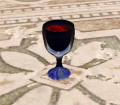 As seen in SL
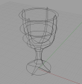 Rhino model
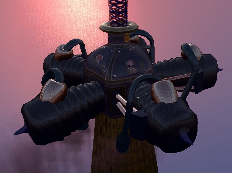
 As seen in SL
 Rhino model
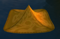
 Rhino model
 As seen in SL
 Rhino model
 Rendered by
 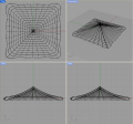 Original
 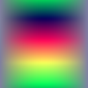 Output from

